Plc Control Circuit Diagram : Convert your relay control schematic into a plc program by ... : Ladder diagram basics #4 (multiple stop start stations).
Dapatkan link
Facebook
X
Pinterest
Email
Aplikasi Lainnya
Plc Control Circuit Diagram : Convert your relay control schematic into a plc program by ... : Ladder diagram basics #4 (multiple stop start stations).. Plc input cards rarely supply power, it means that needs external power supply for the inputs and sensors. Whether you are designing a plc, dcs, dcs, pac, scada, rtu, sis, or pid controller either cabinet based on a machine attached or deployed, the industrial controller. In this article we will discuss about plc circuit diagram of input and output module of plc. Plcs are often used in factories and industrial plants to control motors, pumps, lights, fans, circuit breakers and other machinery. Moreover, their circuits are ideal for extreme.
Below is an input card and ladder logic diagram that shows how to connect an ac input card. How to write plc ladder program | plc program for water tank level control. Plc ladder diagram for single acting and double acting pneumatic cylinders. The actual logic of the control system is established inside the plc by means of a computer program. Plcs are often used in factories and industrial plants to control motors, pumps, lights, fans, circuit breakers and other machinery.
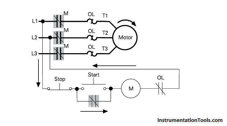
PLC Program for Motor Starter | PLC Motor Control Circuit ... from instrumentationtools.com Dc input plcs have two modes of operation: In the ladder diagram window sketch a program represents the following control circuit. Moreover, their circuits are ideal for extreme. This circuit is under:, circuits, plc circuit diagram l31001 plc input cards rarely supply power, it means that needs external power supply for the inputs and sensors. It mimics circuit diagrams with rungs of logic read left to right. A programmable logic controller (plc) or programmable controller is an industrial digital computer that has been ruggedized and adapted for the control of manufacturing processes. Input modules perform four basic tasks in plc system. Large plc systems consist of a rack into which circuit cards are plugged.
Gain skills for a career in industrial automation and plcs.
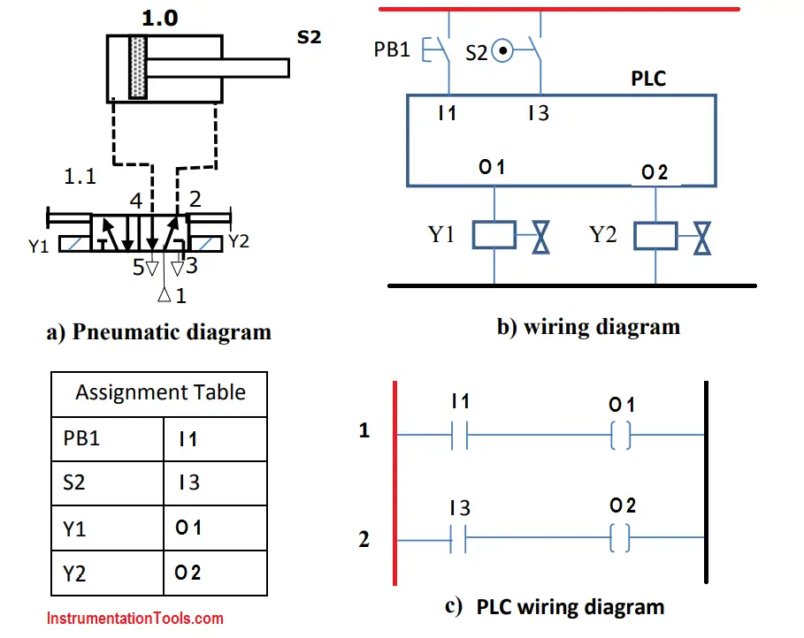
Gain skills for a career in industrial automation and plcs. Below is an input card and ladder logic diagram that shows how to connect an ac input card. Input modules perform four basic tasks in plc system. Cpu (plc controller) systems often require: Familiarity with the instruction set (ladder diagram). This means that it's either true plc programming has never been easier for the original relay control system designers the ladder logic diagram consists of two fundamental parts, which you can see as the vertical and. In this article we will discuss about plc circuit diagram of input and output module of plc. Their circuit is highly reliable and comes under my budget. This circuit is under:, circuits, plc circuit diagram l31001 plc input cards rarely supply power, it means that needs external power supply for the inputs and sensors. Plc ladder diagram for single acting and double acting pneumatic cylinders. Programmable logic controllers (plcs) are small industrial computers with modular components designed to automate customized control processes. Plc stands for programmable logic control. Discuss about plc pneumatic circuit control with different examples.
Their circuit is highly reliable and comes under my budget. In turn, the plc controls the starting and stopping of water pumps and the switching of water valves to manage the water purification and storage processes. Here's how to decipher ladder logic for industrial programming. Programmable logic controllers (plcs) support digital input/output very effectively. It therefore shares common terms with typical pcs like i purchased a plc.
PLC Pneumatic Circuit Control | PLC Programming Pneumatic ... from instrumentationtools.com The first thing that you will notice is that the input for stop is no contact and not nc. Here's how to decipher ladder logic for industrial programming. In electromechanical circuit diagrams, an mcr coil controls several rungs in a circuit by switching on or off the power to those rungs. Experiment #3 programming the plc via ladder logic. In the ladder diagram window sketch a program represents the following control circuit. Whether you are designing a plc, dcs, dcs, pac, scada, rtu, sis, or pid controller either cabinet based on a machine attached or deployed, the industrial controller. Note that symbols are discussed in detail later). Upgrading a machine to plc control may seem like a daunting task.
Familiarity with the instruction set (ladder diagram).
So a plc can also be used to control the operation of a vfd, hence to finally control the connected 3 phase induction motor. Programmable logic controllers (plcs) are small industrial computers with modular components designed to automate customized control processes. .4 plc program for star delta starter, star delta starter control wiring diagram, typical circuit allen bradley plc pwm (pulse width modulation) error codes allen bradley slc controller error codes sensors blck diagram capacitive proximity sensors circuit brakers circuit diagram of motor starter. Moreover, their circuits are ideal for extreme. Master start/stop is also provided to shut down or start the entire process. Cpu (plc controller) systems often require: Experiment #3 programming the plc via ladder logic. Below is an input card and ladder logic diagram that shows how to connect an ac input card. Programmable logic controllers (plcs) support digital input/output very effectively. This is just a small, low resolution samp. Upgrading a machine to plc control may seem like a daunting task. Note that symbols are discussed in detail later). Plc ladder diagram for single acting and double acting pneumatic cylinders.
Ladder diagram basics #4 (multiple stop start stations). A programmable logic controller is a specialized computer used to control machines and processes. .delta starter program in plc ladder diagram control circuit star delta starter ki plc me programming kaise kare plc programming kaise karte hai connect us at: Whether you are designing a plc, dcs, dcs, pac, scada, rtu, sis, or pid controller either cabinet based on a machine attached or deployed, the industrial controller. A programmable logic controller (plc) or programmable controller is an industrial digital computer that has been ruggedized and adapted for the control of manufacturing processes.
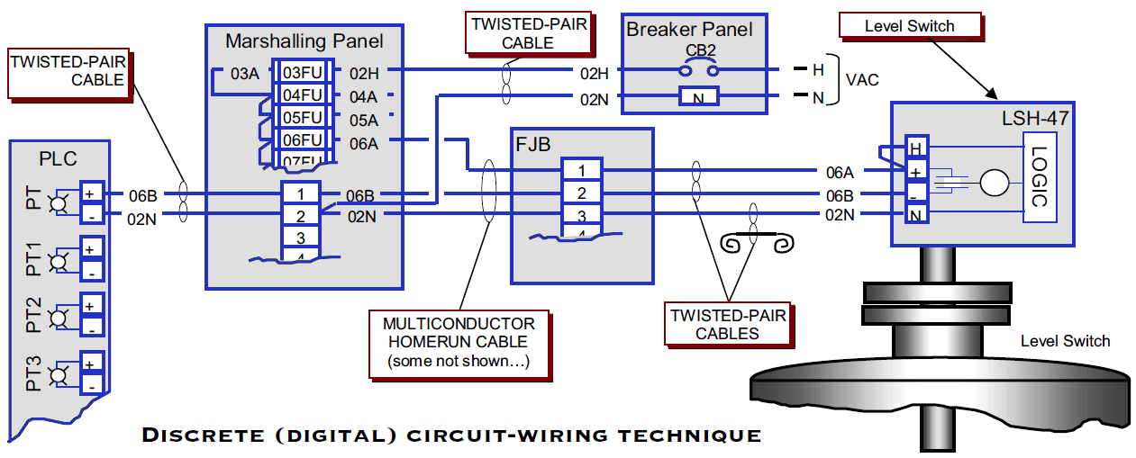
PLC Wiring Diagrams | PLC Digital Signals Wiring Techniques from cdn.instrumentationtools.com Cpu (plc controller) systems often require: All versions of the dvp plc have input / output circuits that can connect to a wide variety of field devices. .delta starter program in plc ladder diagram control circuit star delta starter ki plc me programming kaise kare plc programming kaise karte hai connect us at: Programmable logic controllers (plcs) are small industrial computers with modular components designed to automate customized control processes. Plc stands for programmable logic control. A programmable logic controller (plc) or programmable controller is an industrial digital computer that has been ruggedized and adapted for the control of manufacturing processes. Objectives after successfully completing this laboratory, you should be able to 1. Below is an input card and ladder logic diagram that shows how to connect an ac input card.
The actual logic of the control system is established inside the plc by means of a computer program.
Large plc systems consist of a rack into which circuit cards are plugged. Electric circuit for metal spinning machine controlled by plc. Input modules perform four basic tasks in plc system. Their circuit is highly reliable and comes under my budget. Plc ladder diagram for single acting and double acting pneumatic cylinders. A programmable logic controller is a specialized computer used to control machines and processes. Note that symbols are discussed in detail later). Whether you are designing a plc, dcs, dcs, pac, scada, rtu, sis, or pid controller either cabinet based on a machine attached or deployed, the industrial controller. Let's take a look at the plc program for the above wiring diagram. Below is an input card and ladder logic diagram that shows how to connect an ac input card. Logic circuits are digital, so they produce outputs that are discrete in nature. This program dictates which output gets energized under which input conditions. In turn, the plc controls the starting and stopping of water pumps and the switching of water valves to manage the water purification and storage processes.
2007 Gmc Envoy Fuse Box Diagram - 2002-2009 2004 GMC ENVOY FUSE BOX COVER OEM | eBay : Gmc envoy workshop, repair and owners manuals for all years and models. . There is a fuse location diagram on the underside of the engine bay fuse box cover and also another one in your owner's manual. The problem is that none of these call out anything for the interior fan. Our gmc automotive repair manuals are split into five broad categories; Gmc workshop manuals, gmc owners manuals, gmc wiring diagrams, gmc sales brochures and general miscellaneous gmc downloads. All gmc sierra info & diagrams provided on this site are provided for general information purpose only. Compare 2007 gmc envoy different trims Database contains 1 gmc 2007 envoy manuals (available for free online viewing or downloading in pdf): Car fuse box diagram, fuse panel map and layout. I can't find one anywhere, and why doesn't vw include itinerary their manual?? Remote radio control signal, re...
Arsenal Vs. Everton / Arsenal vs Everton LIVE: Updates and result as fans ... / B.leno, c.chambers, p.mari, r.holding, e.smith rowe, t.partey, d.ceballos, g.xhaka, n.pepe, b.saka, e.nketiah everton: . J.pickford, m.holgate, s.coleman, l.digne, b.godfrey, g.sigurdsson, a.gomes, j.rodriguez, allan, richarlison. Premier league match arsenal vs everton 23.04.2021. So if everton beat arsenal tonight, the gap will grow to six points and carlo ancelotti's men will have a game in hand still. Arsenal fans protesting outside the emirates ahead of game against everton. 1 lucas digne (dl) everton 2. So if everton beat arsenal tonight, the gap will grow to six points and carlo ancelotti's men will have a game in hand still. 1 lucas digne (dl) everton 2. Can mikel arteta's gunners overtake the toffees in the premier league table amid fan protests towards stan kroenke outside the emirates stadium? Arsenal vs everton predictions, football tips and statistics for this m...
Bmw E90 Fuse Box : 2006 2012 Bmw E90 Fuse Box Diagram Circuit Wiring Diagrams - Bmw e90 glove box gently pull the fuse box towards you releasing all the multi plugs from the rear. . Identifying and legend fuse box. Bmw e90 glove box gently pull the fuse box towards you releasing all the multi plugs from the rear. I was going to replace the entire cable as well but. There's a problem loading this menu right now. Fuses are located behind the glove box on the dashboard. Fuse box location and diagrams: Fuses are located behind the glove box on the dashboard. E90 voltage supply & bus systems. Washer, electric fan, bell, oil indicator, headlamp, fog light, alarm, heater, wiper, steering, door lock, power window, fuel pump indicator, heated seat, seat belt, power mirror. Fuse box info 1 год назад. 4a66 Bmw E92 Wiring Diagram Audio Wiring Resources from imgv2-1-f.scribdassets.com ...


Komentar
Posting Komentar