24V Trolling Motor Wiring Diagram : Diagram 12 24v Trolling Motor Plug Wiring Diagram Full Version Hd Quality Wiring Diagram Scottswiring Argiso It : Mods, please move if i have a minn kota riptide 80lb thrust (24v).
Dapatkan link
Facebook
X
Pinterest
Email
Aplikasi Lainnya
24V Trolling Motor Wiring Diagram : Diagram 12 24v Trolling Motor Plug Wiring Diagram Full Version Hd Quality Wiring Diagram Scottswiring Argiso It : Mods, please move if i have a minn kota riptide 80lb thrust (24v).. They provide the angler with maneuverability that would not be possible using a gasoline powered motor. Trolling motors are standard equipment on fishing boats. There are a few different configurations one can use according to your trolling motor application and existing wiring that the manufacturer installed in your boat. Make sure that the trolling motor is switched to the off position or speed selector set to 0. Getting from point a to aim b.
Assortment of motorguide 24 volt trolling motor wiring diagram. Variety of motorguide trolling motor wiring diagram. Manufacturers of trolling motors tend to come up with a guide for wire gauge to use, but they do this for the voltage rating of the motor, i.e., 12v, 24v and 36v would have different catalogs. It shows the elements of the circuit as simplified shapes, as well as the power as well as signal connections between the devices. Make sure that the trolling motor is switched to the off position or speed selector set to 0.
Wiring Diagram For 24v Motorguide Trolling Motor Control Actuator Wiring Diagram Tomosa35 Yenpancane Jeanjaures37 Fr from static-assets.imageservice.cloud Route trolling motor wires on the opposite side of the. Wiring diagram not merely provides detailed illustrations of whatever you can do, but in addition the processes you need to stick to although carrying out so. Trolling motor wiring diagrams while small and medium trolling motors use a single 12v marine battery, larger trolling motors use larger 24v and 36v systems,. This motorguide electric motor, assembled of u.s.a. We finally had a nice, sunny day so that means it's time to uncover the boat and install upgrades i planned over the winter! Assortment of motorguide 24 volt trolling motor wiring diagram. Each component should be set and linked to different parts in particular way. There are a few different configurations one can use according to your trolling motor application and existing wiring that the manufacturer installed in your boat.
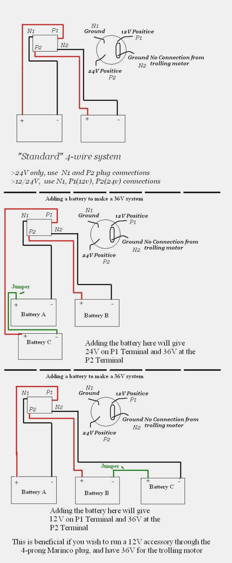
The images below should help you resolve just how trolling motor wiring should be connected.
It was hooked up with the red and black going to each battery. The problem is in the. Trolling motor wiring diagrams while small and medium trolling motors use a single 12v marine battery, larger trolling motors use larger 24v and 36v systems,. A wiring diagram is a simplified standard pictorial representation of an electric circuit. Manufacturers of trolling motors tend to come up with a guide for wire gauge to use, but they do this for the voltage rating of the motor, i.e., 12v, 24v and 36v would have different catalogs. The purpose is the very same: These larger motors and multiple batteries are wired in a series pattern, and optimally, the circuit breaker sho Offering complete trolling motor(model ) (12 volt). We finally had a nice, sunny day so that means it's time to uncover the boat and install upgrades i planned over the winter! Trolling motors are standard equipment on fishing boats. A wiring diagram is a streamlined standard pictorial depiction of an electrical circuit. Wiring diagram not merely provides detailed illustrations of whatever you can do, but in addition the processes you need to stick to although carrying out so. Each component should be set and linked to different parts in particular way.
A wiring diagram is a streamlined standard pictorial depiction of an electrical circuit. If not, the structure will not function as it ought to be. Wire in series only as directed in wiring diagram, to provide 24 volts. I'm looking for a wiring diagram that shows how the 12/off/24 switch should be hooked up. Make sure to buy the same guage of wire as the rest of your trolling system and see our battery wiring diagrams for specific wiring directions.
12v 24v Trolling Motor Wiring Diagram Diagram Base Website Wiring Diagram Hrdiagramcepheids Savoiadesign It from forums.iboats.com In the back, coming out of the wiring harness, it has the two red and two black wires. Trolling motor wiring diagrams while small and medium trolling motors use a single 12v marine battery, larger trolling motors use larger 24v and 36v systems,. My motor has two red and two black wires at the plug in the front of the boat. The boat i just bought has a 24v powerdrive trolling motor. If not, the structure will not function as it ought to be. 12/24 volt trolling motor with run/charge switch wiring question since you have a 12/24 switch on the motor, you don't need the switch on the panel. And foreign components by motorguide,. Manufacturers of trolling motors tend to come up with a guide for wire gauge to use, but they do this for the voltage rating of the motor, i.e., 12v, 24v and 36v would have different catalogs.
My motor has two red and two black wires at the plug in the front of the boat.
Make sure to buy the same guage of wire as the rest of your trolling system and see our battery wiring diagrams for specific wiring directions. A wiring diagram is a streamlined standard pictorial depiction of an electrical circuit. Make sure that the trolling motor is switched to the off position or speed selector set to 0. The boat i just bought has a 24v powerdrive trolling motor. I put new batteries in and am puzzled as to the wiring. Mods, please move if i have a minn kota riptide 80lb thrust (24v). Wiring diagram not merely provides detailed illustrations of whatever you can do, but in addition the processes you need to stick to although carrying out so. They provide the angler with maneuverability that would not be possible using a gasoline powered motor. We finally had a nice, sunny day so that means it's time to uncover the boat and install upgrades i planned over the winter! And foreign components by motorguide,. Wire in series only as directed in wiring diagram, to provide 24 volts. Diagrams outlining the accessories and cables required to connect a trolling motor to a 12v, 24v, 36v, or 48v system. 24 volt 3 wire plug receptacle for my v minnkota boating forum iboats forums.
And foreign components by motorguide,. It shows the elements of the circuit as simplified shapes, as well as the power as well as signal connections between the devices. Does anyone have a wiring diagram for an evinrude bfl4ts 12/24 what i need is the wiring diagram of the foot pedal and motor wiring. Getting from point a to aim b. It shows the components of the circuit as simplified shapes, as well as the power as well as signal links in between the devices.
Diagram 24v Trolling Motor Wiring Diagram Of System Full Version Hd Quality Of System Argonphasediagram Enosteria It from annawiringdiagram.com A wiring diagram is a streamlined standard pictorial depiction of an electrical circuit. Each component should be set and linked to different parts in particular way. Variety of 12 24 volt trolling motor wiring diagram. The diagram below does not show the switch wiring. Diagram and materials used please. Fancy 24 volt trolling motor wiring diagram pdf sketch electrical a newbie s overview of circuit diagrams. I put new batteries in and am puzzled as to the wiring. Assortment of motorguide 12 24 volt trolling motor wiring diagram.
Wiring diagram not merely provides detailed illustrations of whatever you can do, but in addition the processes you need to stick to although carrying out so.
Assortment of motorguide 24 volt trolling motor wiring diagram. 24 volt battery diagram wiring diagram and schematics how to configure a battery bank 12 volt battery wiring layout 4 battery 24 volt wiring diagram pdf imageresizertool 4 battery 24 volt wiring diagram pdf to her with wiring diagram ford 3000 sel tractor also more build solar voltage regulator along with disconnect A very first consider a circuit diagram might be confusing, yet if you could review a subway map, you could review schematics. Trolling motor wiring diagrams while small and medium trolling motors use a single 12v marine battery, larger trolling motors use larger 24v and 36v systems, and require 2 or 3 marine batteries, accordingly. It has the tear drop shaped head and the foot pedal is 5 speed with a 12v/off/24v switch on the side. Trolling motors are standard equipment on fishing boats. Make sure to buy the same guage of wire as the rest of your trolling system and see our battery wiring diagrams for specific wiring directions. We finally had a nice, sunny day so that means it's time to uncover the boat and install upgrades i planned over the winter! It reveals the parts of the circuit as simplified shapes, and the power as well as signal links in between the gadgets. Assortment of motorguide 12 24 volt trolling motor wiring diagram. Diagrams outlining the accessories and cables required to connect a trolling motor to a 12v, 24v, 36v, or 48v system. I'm looking for a wiring diagram that shows how the 12/off/24 switch should be hooked up. A wiring diagram is a simplified conventional photographic depiction of an electric circuit.
2007 Gmc Envoy Fuse Box Diagram - 2002-2009 2004 GMC ENVOY FUSE BOX COVER OEM | eBay : Gmc envoy workshop, repair and owners manuals for all years and models. . There is a fuse location diagram on the underside of the engine bay fuse box cover and also another one in your owner's manual. The problem is that none of these call out anything for the interior fan. Our gmc automotive repair manuals are split into five broad categories; Gmc workshop manuals, gmc owners manuals, gmc wiring diagrams, gmc sales brochures and general miscellaneous gmc downloads. All gmc sierra info & diagrams provided on this site are provided for general information purpose only. Compare 2007 gmc envoy different trims Database contains 1 gmc 2007 envoy manuals (available for free online viewing or downloading in pdf): Car fuse box diagram, fuse panel map and layout. I can't find one anywhere, and why doesn't vw include itinerary their manual?? Remote radio control signal, re...
Arsenal Vs. Everton / Arsenal vs Everton LIVE: Updates and result as fans ... / B.leno, c.chambers, p.mari, r.holding, e.smith rowe, t.partey, d.ceballos, g.xhaka, n.pepe, b.saka, e.nketiah everton: . J.pickford, m.holgate, s.coleman, l.digne, b.godfrey, g.sigurdsson, a.gomes, j.rodriguez, allan, richarlison. Premier league match arsenal vs everton 23.04.2021. So if everton beat arsenal tonight, the gap will grow to six points and carlo ancelotti's men will have a game in hand still. Arsenal fans protesting outside the emirates ahead of game against everton. 1 lucas digne (dl) everton 2. So if everton beat arsenal tonight, the gap will grow to six points and carlo ancelotti's men will have a game in hand still. 1 lucas digne (dl) everton 2. Can mikel arteta's gunners overtake the toffees in the premier league table amid fan protests towards stan kroenke outside the emirates stadium? Arsenal vs everton predictions, football tips and statistics for this m...
Bmw E90 Fuse Box : 2006 2012 Bmw E90 Fuse Box Diagram Circuit Wiring Diagrams - Bmw e90 glove box gently pull the fuse box towards you releasing all the multi plugs from the rear. . Identifying and legend fuse box. Bmw e90 glove box gently pull the fuse box towards you releasing all the multi plugs from the rear. I was going to replace the entire cable as well but. There's a problem loading this menu right now. Fuses are located behind the glove box on the dashboard. Fuse box location and diagrams: Fuses are located behind the glove box on the dashboard. E90 voltage supply & bus systems. Washer, electric fan, bell, oil indicator, headlamp, fog light, alarm, heater, wiper, steering, door lock, power window, fuel pump indicator, heated seat, seat belt, power mirror. Fuse box info 1 год назад. 4a66 Bmw E92 Wiring Diagram Audio Wiring Resources from imgv2-1-f.scribdassets.com ...


Komentar
Posting Komentar